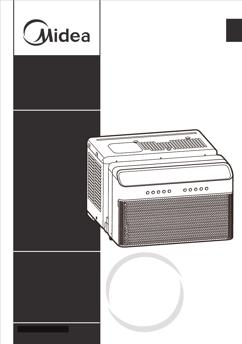
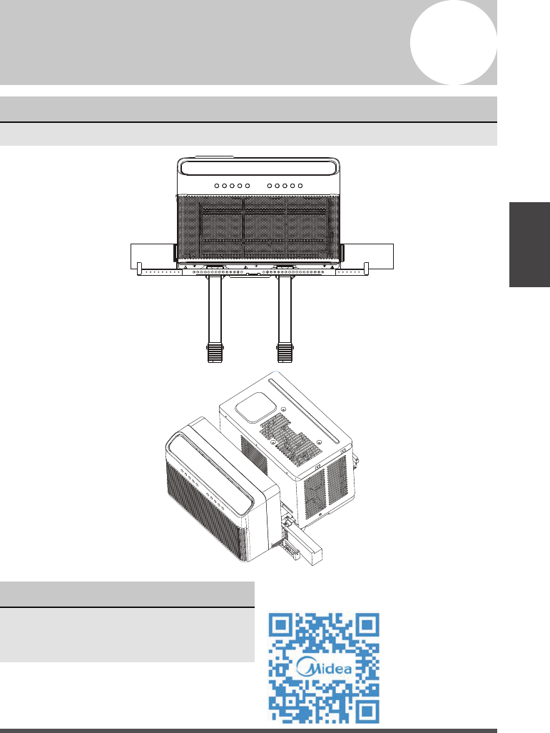
Window Air Conditioner
version B - 02 - 2020
MAW12V1DWT
MAW10V1DWT
MAW08V1DWT
midea.com
USER MANUAL
en
MAW
Warning notices: Before using
this product, please read this
manual carefully and keep it for
future reference. For additional
support, please call customer
service at 1-866-646-4332.
The design and specifications are
subject to change without prior
notice for product improvement.
Consult with your dealer or
the manufacturer for details.
Capacity: 8000 ~ 12000BTU/h
version D - 03 - 2020
Free 3 months
extension* of the
original limited warranty
period! Simply text a
picture of your proof of
purchase to:
1-844-224-1614
*The warranty extension is for the
three months immediately following
the completion of the product’s
original warranty period.

Page 2
Read This Manual
Inside you’ll find many helpful hints on how to use and maintain your air conditioner
properly. Just a little preventive care on your part can save you a great deal of time
and money over the life of your air conditioner. You’ll find many answers to common
problems in the troubleshooting tips - you should be able to fix most of them quickly
before calling service. These instructions may not cover every possible condition of
use, so common sense and attention to safety is required when installing, operating
and maintaining this product.
• For support, please call the Service Center at 1-866-646-4332.
• This appliance is not intended for use by people (including children) with reduced
physical, sensory, or mental capabilities or lack of experience and knowledge,
unless they have been given supervision or instruction concerning use of the
appliance by a person responsible for their safety.
• Children should be supervised to ensure that they do not play with the appliance.
• The appliance shall be installed in accordance with national wiring regulations.
• Do not operate your air conditioner in a wet room such as a bathroom or laundry room.
Owner’s Manual
0
1
2
3
4
5
CAUTION
Safety Precautions ............................................................................ 3
Operating Instructions ..................................................................... 8
Installation Instructions ...................................................................
13
Care and Cleaning ........................................................................... 24
Troubleshooting Tips ...................................................................... 25
Warranty ............................................................................................ 27
Page 3
Safety Precautions
Safety
Precautions
To prevent injury to the user or other people and property damage, the instructions
shown here must be followed. Incorrect operation due to ignoring of instructions may
cause harm or damage. The level of risk is shown by the following indications.
WARNING
• Be sure the air conditioner has been securely and correctly installed according to
the installation instructions in this manual. Save this manual for possible future use
in removing or installing this unit.
• Plug in power cord plug properly.
Otherwise, it may cause electric shock or fire due to excess heat generation.
• Do not modify power cord length or share the outlet with other appliances as it
may cause electric shock or fire due to overheating.
• Always ensure effective grounding.
Incorrect grounding may cause electric shock.
• Unplug the unit if you notice unusual sounds or smells or smoke coming from it.
A damaged product may cause fire and electric shock.
• Ventilate room before operating the air conditioner if there is a gas leakage from
another appliance.
• Do not operate or stop the unit by inserting or pulling out the power cord plug.
• Do not operate with wet hands or in very humid enviroments.
It may cause electric shock.
• Do not allow water to come into contact with any electric parts.
It may cause failure or electric shock.
• Do not use the socket if it is loose or damaged.
It may cause fire and electric shock.
• Do not use or keep the power cord close to heating appliances.
It may cause fire and electric shock.
• Do not use any devices or materials for installation that are not recommended in
this manual.
WARNING
This symbol indicates a hazardous situation which, if not
avoided, could result in death or serious injury.
CAUTION
This symbol indicates a hazardous situation, which, if not
avoided, could result in minor or moderate injury.
NOTICE
This symbol addresses practices not related to physical
injury.

Page 4
WARNING
• Do not disassemble or modify unit.
It may cause failure and electric shock.
• Do not damage or use an alternate power cord.
It may cause fire and electric shock.
If the power cord is damaged, it must be replaced by the manufacturer or an
authorized service center or a similarly qualified person in order to avoid a hazard.
• Do not direct airflow straight into persons to avoid possible health hazard.
• Do not open the unit during operation.
It may cause electric shock.
• Do not use the power cord near flammable gas or combustibles, such as gasoline,
benzene, thinner, etc.
It may cause an explosion or fire.
• Do not let children hang on the air conditioner or bracket.
A serious injury may occur.
• Avoid fire hazard or electric shock. Do not use an extension cord or an adaptor
plug. Do not remove any prongs from the power cord.
• Be sure the air conditioner is properly grounded. To minimize shock and fire
hazards, proper grounding is important. The power cord is equipped with a
three-prong grounding plug for protection against shock hazards.
• Your air conditioner must be used in a properly grounded wall receptacle. If the
wall receptacle you intend to use is not adequately grounded or protected by a
time delay fuse or circuit breaker, have a qualified electrician install the proper
receptacle. Ensure the receptacle is accessible after the unit installation.
• Be sure the electrical service is adequate for the model you have chosen. This
information can be found on the serial plate, which is located on the side of the
cabinet and behind the grille.
CAUTION
• When the air filter is to be removed, do not touch the m etal parts of the unit.
It may cause injury.
• When the unit needs cleaning, switch off, and turn off the circuit breaker.
Do not clean unit when power is on as it may cause fire, electric shock or injury.
• Do not place obstacles around air inlets or inside of air outlet.
It may cause failure or accident.
• Clean with a soft cloth only. Do not use strong detergents that contain wax or
thinners as it may damage the product.
• Use caution when unpacking and installing. Sharp edges could cause injury.
• Do not clean the air conditioner with water.
Water may enter the unit and degrade the insulation which could lead to
electric shock.
Safety
Precautions

Page 5
Safety
Precautions
CAUTION
• Do not put a pet or house plant where it will be exposed to direct air flow.
This could injure the pet or harm the plant.
• Hold the plug by the head of the power plug when taking it out.
Otherwise, it may cause electric shock and damage.
• Ensure that the installation is properly secured to prevent the product from
potentially falling.
• Do not place heavy objects on the power cord and ensure that the cord is not
compressed.
Otherwise, there is danger of fire or electric shock.
• If water is spilled on the unit, turn off the unit and switch off the circuit breaker.
Isolate supply by taking the power-plug out and contact a qualified service
technician.
• Do not use near gas stove or other gas burning appliances, as air flow may affect
gas combustion.
• Do not use for any purpose other than room comfort.
Do not use this air conditioner to preserve precision devices, food, pets, plants,
and art objects. It may cause deterioration.
• Turn off the main power switch if the unit is not to be used for an extended time.
• Always insert the filters securely. Clean filter once every two weeks.
Operation without filters may cause failure.
• Do not drink water drained from the air conditioner.
Page 6
Safety
Precautions
NOTICE
• Do not use this device to turn the unit on or off.
• Always make sure the RESET button is pushed in for correct operation.
• The power supply must be replaced if it fails to reset when either the TEST button
is pushed, or it can not be reset. Please contact Customer Service.
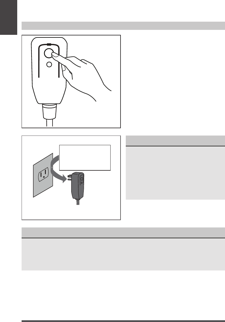
NOTICE
The power supply cord with this
air conditioner contains a current
detection device designed to reduce
the risk of fire.
In the event that the power supply
cord is damaged, it can not be
repaired. It must be replaced with a
cord from the manufacturer.
Grounding type wall receptacle
Do not, under any
circumstances, cut,
remove or bypass
the grounding prong.
Power supply cord with 3-prong grounding
plug and current detection device.
The power supply cord contains a current
device that senses damage to the power
cord. Test your power supply cord as
follows:
1. Plug in the air conditioner.
2. The power supply cord will have TWO
buttons on the plug head. Press the
TEST button. You will notice a click as
the RESET button pops out.
3. Press the RESET Button. You will
notice a click as the button engages.
4. The power supply cord is now
supplying electricity to the unit. (On
some products this is also indicated
by a light on the plug head.)
RESET
TEST
Plug in &
press RESET
Operation of Current Device
Page 7
Safety
Precautions
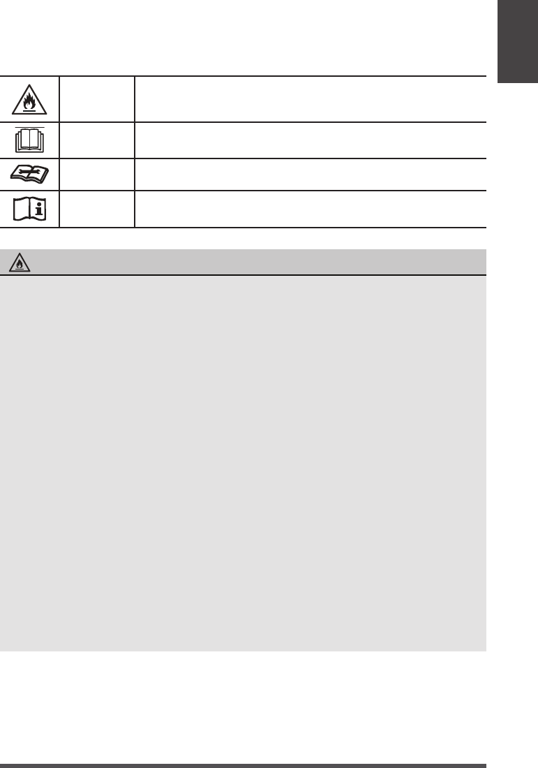
WARNING
This symbol shows that this appliance used a flammable
refrigerant. If the refrigerant is leaked and exposed to an
external ignition source, there is a risk of fire.
CAUTION
This symbol shows that the operation manual should be read
carefully.
CAUTION
This symbol shows that a service personnel should be handling
this equipment with reference to the installation manual.
CAUTION
This symbol shows that information is available such as the
operating manual or installation manual.
EXPLANATION OF SYMBOLS DISPLAYED ON THE UNIT
• Do not try to accelerate the defrosting process or methods of cleaning that are
not recommended by the manufacturer.
• The appliance shall be stored in a room without a continuously operating ignition
source (for example, open flames or an operating gas appliance) or an ignition
source (for example, an operating electric heater) close to the appliance. The
appliance shall also be stored in a room without ignition sources.
• Do not pierce or burn.
• Be aware that the refrigerants may not contain an odor.
• Compliance with national gas regulations shall be observed.
• Keep ventilation openings clear of obstruction.
• The appliance shall be stored in a well-ventilated area where the room size
corresponds to the room area as specied for operation.
• Unit is only to be serviced by a Midea authorized servicer, please call Customer
Service at 1-866-646-4332 for support.
• Flammable refrigerant R32 is used within air conditioner. Please follow the
instructions carefully to handle, install, clean, and service the air conditioner
to avoid damage or hazard. Do not dispose of air conditioner in regular trash.
Contact qualified agency for proper disposal.
• No open fire or devices that generate spark/arcing shall be around the air
conditioner to avoid causing ignition of the flammable refrigerant used. Please
follow the instructions carefully to store or maintain the air conditioner to
prevent mechanical damage from occurring.
• Be aware that refrigerants may not contain an odor.
WARNING
Page 8
1
Operating Instructions
Normal Sounds
Sound Performance
Sound of Rushing Air
In front of the unit, you
may hear the sound of
rushing air being moved
by the fan.
High Pitched Chatter
+LJKHI´FLHQF\FRPSUHVVRUV
PD\KDYHDKLJKSLWFKHG
VRXQGGXULQJFRROLQJF\FOH
Vibration
Unit may vibrate and
PDNHQRLVHEHFDXVH
RISRRUZDOORU
ZLQGRZFRQVWUXFWLRQ
RULQFRUUHFW
LQVWDOODWLRQ
Trickling Sound
'URSOHWVRIZDWHUKLWWLQJ
FRQGHQVHUGXULQJQRUPDO
RSHUDWLRQPD\FDXVHD
WULFNOLQJVRXQG
Gurgle/Hiss
*XUJOLQJRUKLVVLQJ
noises may be heard
GXHWRUHIULJHUDQWµRZLQJ
WKURXJKHYDSRUDWRU
GXULQJQRUPDORSHUDWLRQ
Model Number Sound Power, dB(A)*
MAW08V1QWT 42
MAW10V1QWT 42
MAW12V1QWT 42
The following table shows the sound performance data for these window air conditioners.
Please use your specific model number to reference the correct sound power number
in the table.
* per ISO 3744 at low fan speed
Operating
Instructions
Page 9
NOTICE
The cool circuit has an automatic 3 minutes time delayed start if the unit is turned off and on
quickly. This prevents overheating of the compressor and possible circuit breaker tripping.
Air Conditioner Operation
WARNING
To reduce the risk of fire, electrical shock, or injury to people or property, read the
SAFETY PRECAUTIONS before operating this appliance.
To begin operating the air conditioner, follow these steps:
1. Plug in the air conditioner (be sure to follow the power cord instructions on Page 6).
2. Turn the power on to the air conditioner, using the ON/OFF button.
3. Set the thermostat to the coldest temperature setting.
4. Select the Cool mode setting.
5. Adjust the louver for comfortable air flow (see Air Directional Louvers).
6. Once the room has cooled, adjust the thermostat to the setting you find most comfortable.
7. Make sure the air flow inside and outside is not obstructed by anything.
Cooling Operation
Outdoor temp.: 64°F ~ 109°F / 18°C ~ 43°C
(64°F ~ 125°F / 18°C ~ 52°C for special tropical models)
Indoor temp.: 60°F ~ 90°F / 16°C ~ 32°C
NOTICE
• The relative humidity of room should be less than 80%. If the unit is used in a condition with
a relative humidity over 80%, there will be condensed water on the surface of the unit.
• Performance may be reduced outside of these operating temperatures.
Operating
Instructions
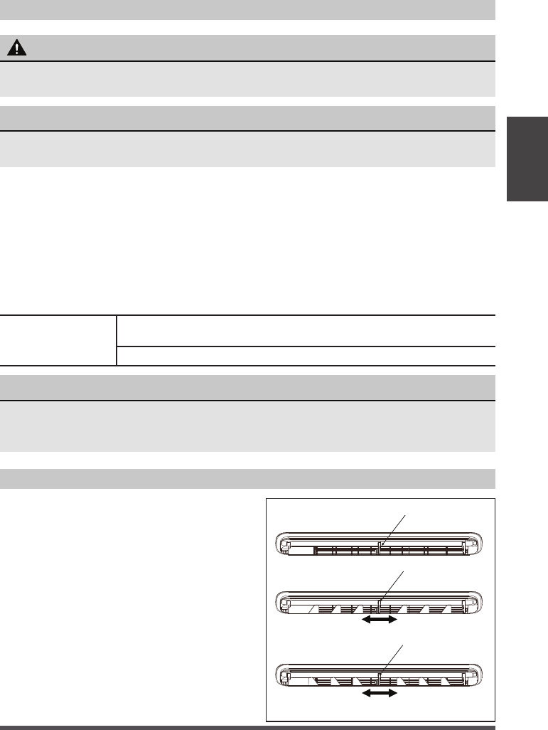
Air Directional Louvers
The louvers will allow you to direct the air
flow up or down (on some models) and left
or right throughout the room as needed.
Pivot horizontal louvers until the desired
up/down direction is obtained.
Move the louvers from side to side until the
desired left/right direction is obtained.
Air Direction
Lever
Lever
Lever
Air Direction
Page 10
Operating
Instructions
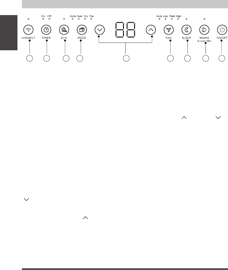
ELECTRONIC CONTROL OPERATING INSTRUCTIONS
3. (TIMER) Button
• Press Timer button, the TIMER ON or
TIMER OFF indicator light illuminates.
lt indicates the Auto Start or Auto Stop
program is initiated. For some units,
continuing to press the Timer button
will cancel the timer settings.
• Press or hold the UP (
) or DOWN ( )
button to change the Auto time by 0.5
hour increments, up to 10 hours, then
at 1 hour increments up to 24 hours.
The display will count down the time
remaining until start.
• The selected time will register in
5 seconds, and the system will
automatically revert back to display
the previous temperature setting or
room temperature when the unit is
on. When the unit is off, there is no
display.
• Turning the unit ON or OFF at any time
or adjusting the timer setting to 0.0
will cancel the Auto Start/Stop timed
program.
1. (ON/OFF) Button
Press ON/OFF button to turn unit on or off.
2. (CONNECT) Button
For the first time using the WiFi function,
press the button for 3 seconds to initiate
the WiFi connection mode. The LED
DISPLAY shows ‘AP’ to indicate you can
set up the WiFi connection. Please also
refer to the included WiFi manual for
further instructions.
If connection (router) is successful
within 8 minutes, the unit will exit WiFi
connection mode automatically and the
CONNECT indicator illuminates.
If connection failed within 8 minutes,
the unit exits WiFi connection mode
automatically.
After WiFi connection is successful, you
can press and hold CONNECT and DOWN
(
) buttons at the same time for 3
seconds to turn off WiFi function and the
LED DISPLAY shows ‘OF’ for 3 seconds,
press CONNECT and UP (
) buttons at
the same time to turn on WiFi function and
the LED DISPLAY shows ‘On’ for 3 seconds.
1
2
5
3 4
6 7 8 9
Before you begin, thoroughly familiarize yourself with the control panel as shown
below and all its functions, then follow the symbol for the functions you desire. The
unit can be controlled by the unit control panel, with the remote control, smart
phone app, or voice control

Page 11
Operating
Instructions
4. (EC0) Button
Press ECO button to initiate this function.
This function is available on COOL, DRY,
and AUTO (only AUTO-COOLING and
AUTO-FAN) modes. The fan will continue
to run for 3 minutes after the compressor
shuts off.
The fan then cycles on for 2 minutes
at 10 minute intervals until the room
temperature is above the set temperature,
at which time the compressor turns back
on and Cooling Starts.
5. (MODE) Button
• To choose operating mode, press
MODE button. Each time you press
the button, a mode is selected in a
sequence that goes from Auto, Cool,
Dry and Fan. The indicator light beside
the button will be illuminated and
remain on once that mode is selected.
• The unit will automatically initiate the
Energy Saver function under Cool,
Dry, and Auto (only Auto-Cooling and
Auto-Fan) modes.
To operate on AUTO feature:
• When you set the air conditioner to
AUTO mode, it will automatically
select cooling or fan only operation,
depending on what temperature you
have selected and the current room
temperature.
• The air conditioner will control room
temperature automatically according
based on the temperature you’ve set.
• In this mode, the fan speed cannot
be adjusted, it starts automatically
at a speed according to the room
temperature.
To operate on COOL mode:
• Choose Cool Mode to set the cooling
function. Use the UP (
) or DOWN
(
) buttons to choose the desired
temperature. When Cool Mode is
selected, the fan speed can be adjusted
by pressing the FAN button.
To operate on DRY mode:
• In this mode, the air conditioner will
generally operate as a dehumidifier.
Since the conditioned space is a closed
or sealed area, some degree of cooling
will continue. On Dry mode, the fan
speed is not adjustable.
To operate on FAN mode:
• Use this function only when cooling
is not desired, such as for room air
circulation or to exhaust stale air (on
some models). (Remember to open
the vent during this function, but keep
it closed during cooling for maximum
cooling efficiency.) You can choose any
fan speed you prefer.
• In Fan Only mode, the temperature can
not be adjusted.
6. (UP/DOWN) Button
Press UP (
) or DOWN ( ) button to
change temperature setting.
7. (FAN SPEED) Button
Press FAN button to select the Fan Speed
in four steps - Auto, Low, Med or High.
Each time the button is pressed, the fan
speed mode is shifted.
8. (SLEEP) Button
Press SLEEP button to initiate the
sleep mode. In this mode the selected
temperature will increase (in cooling
mode) by 2°F/1 (or 2)°C 30 minutes after
the mode is selected. The temperature
will then increase (in cooling mode) by
another 2°F/1(or 2)°C after an additional
30 minutes.
This new temperature will be maintained
for 7 hours before it returns to the
originally selected temperature.
This ends the Sleep mode and the unit
will continue to operate as originally
programmed. The Sleep mode program can
be cancelled at any time during operation
by pressing the SLEEP button again.
Page 12
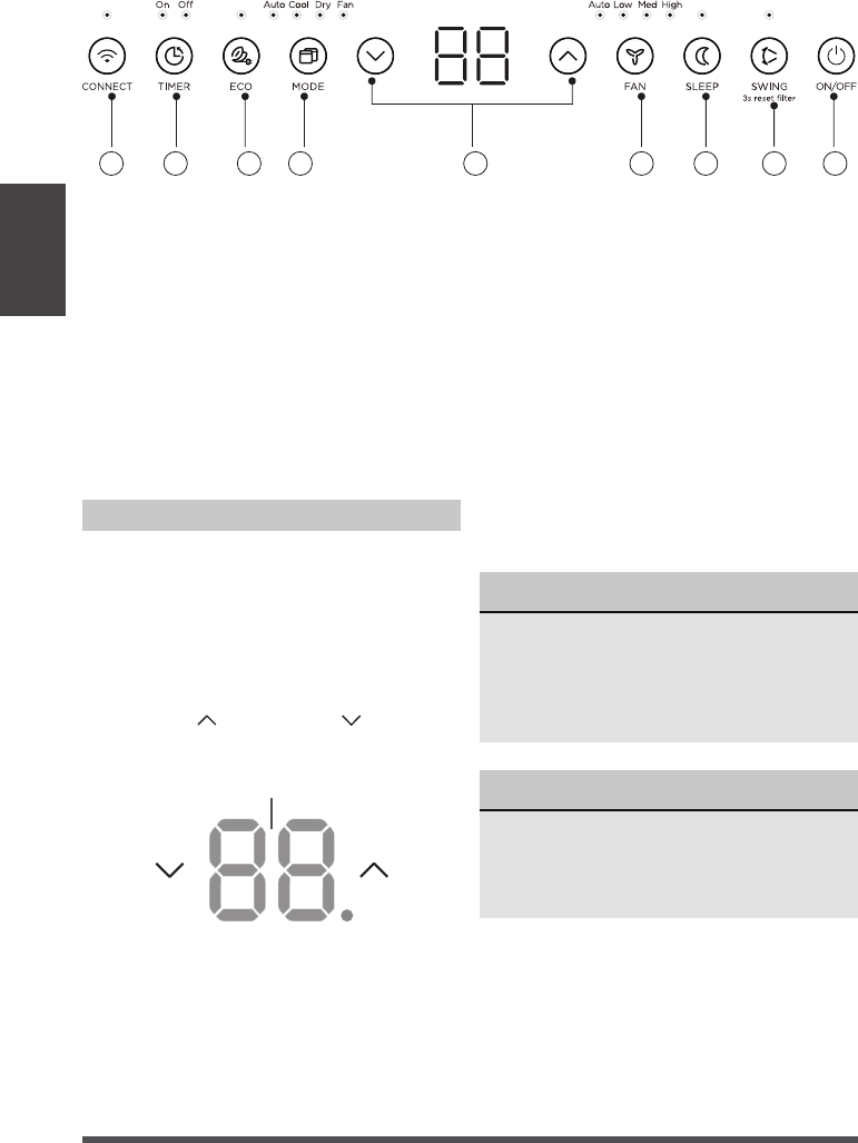
LED Display:
Shows the set temperature in “°C” or
“°F” and the Auto-timer settings. While
on Fan Only mode, it shows the room
temperature. If the room temperature is
too high or low, it will display “ HI” or “ LO”.
To convert from one to the other, press and
hold the UP (
) and DOWN ( ) buttons
at the same time for 3 seconds.
Error codes:
The unit may stop operation or continue
to run safely. If the error codes appear,
wait for about 10 minutes.
The problem may resolve itself. If not,
disconnect the power, then connect it
again. Turn the unit on.
If the problem persists, disconnect the
power and contact customer service.
Error code appears and begins with the
letters as the following in the window
display of indoor unit:
EH(xx), EL(xx), EC(xx) , PH(xx), PL(xx),
PC(xx).
Display
NOTICE
If your problem persists after performing
the checks and diagnostics above, turn
off your unit immediately and contact
an authorized service center by calling
1-866-646-4332.
NOTICE
If the unit turns off unexpectedly due to
the power being cut, it will automatically
restart with the previous function setting
when the power resumes.
DISPLAYS
Operating
Instructions
9. (SWING) Button
Used to initiate the Auto swing feature.
When the operation is ON, pressing the
SWING button can stop the louver at the
desired angle.
Press SWING button for 3 seconds to
initiate the lter feature. This feature is a
reminder to clean the Air Filter for more
ecient operation. The LED (the light above
the button) will illuminate after 250 hours
of operation.
12
5
3 4
6 7 8 9
Page 13
2
Installation Instructions
Installation
Instructions
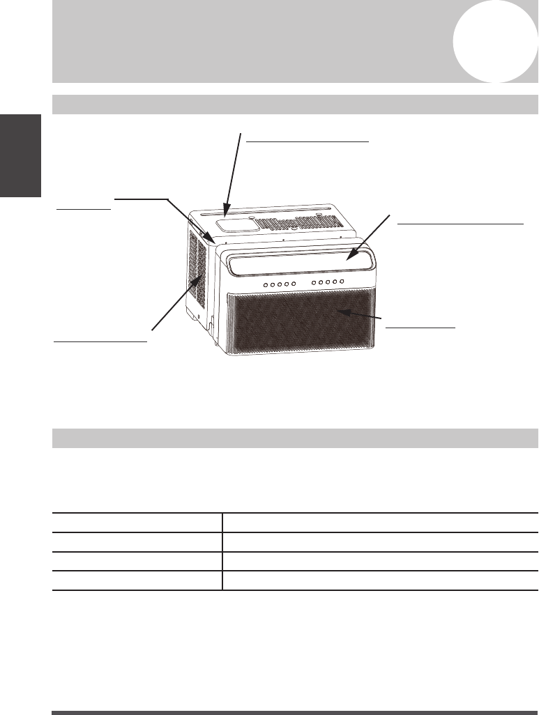
NOTICE
The unit you purchased may look like the following:
NOTICE
All the illustrations in this manual are
for explanation purpose only. The actual
installation may vary.
Scan the following QR code for an
installation video.
Page 14
Installation
Instructions
WARNING - Before You Begin
Read these instructions completely
and carefully.
• IMPORTANT - Save these instructions.
• IMPORTANT - Observe all governing
codes and ordinances.
We recommend that two people
install this product.
Proper installation is the responsibility
of the installer.
Product failure due to improper
installation is not covered under the
Limited Warranty.
You MUST use all supplied parts and
use proper installation procedures as
described in these instructions when
installing this air conditioner.
Do not, under any circumstances, cut
or remove the third (ground) prong
from the power cord.
Do not change the plug on the power
cord of the air conditioner.
Aluminum house wiring may present
special problems - consult a qualified
electrician.
When handling unit, be careful to
avoid cuts from sharp metal edges and
aluminum fins on front and rear coils.
Please wear cut-resistant gloves.
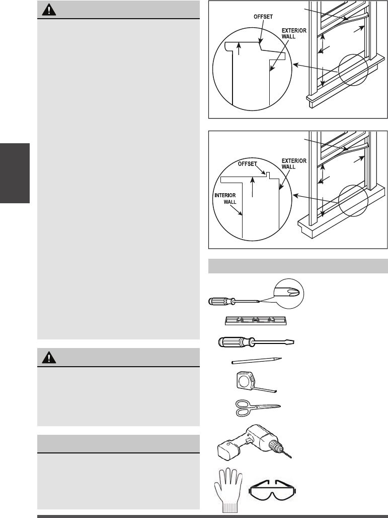
Tools You Will Need
WINDOW REQUIREMENTS
Your air conditioner is designed
to install in standard double hung
windows with opening widths of 22
to 36 inches (558mm to 914mm) and
a window height of 13.75” (349mm).
Wooden Windows
INNER
WINDOW SILL
INTERIOR
WALL
13.75" min
(349 mm)
22" to 36"
(558 mm to 914mm)
SEAL FOAM
Vinyl-Clad Windows
INNER
WINDOW SILL
13.75" min
(349 mm)
22" to 36"
(558 mm to 914mm)
SEAL FOAM
Flathead
Screwdriver
Pencil
Ruler or tape measure
Scissors or knife
Drill and 1/8” drill bit
Phillips
Screwdriver
Level
Proper PPE
NOTICE
You will probably want to clean both
sides of the glass first. If the window
is a triple-track type with a screen
panel included, remove the screen
completely before installation.
Page 15
Installation
Instructions
Lower sash must open sufficiently to allow a clear vertical opening of 13.5 inches. Side
louvers and the rear of the AC must have clear air space to allow enough airflow through
the condenser for heat removal. The rear of the unit must be outdoors, not inside a
building or garage.
Remove the air conditioner and hardware from the carton and place on a flat surface.
1. INSTALL THE SUPPORT BRACKET
NOTICE
Save carton and these Installation Instructions for future reference. The carton is the best
way to store unit during winter, or when not in use.
NOTICE
If any piece of hardware is missing, DO
NOT INSTALL THE PRODUCT, and call
customer service at 1-866-646-4332.
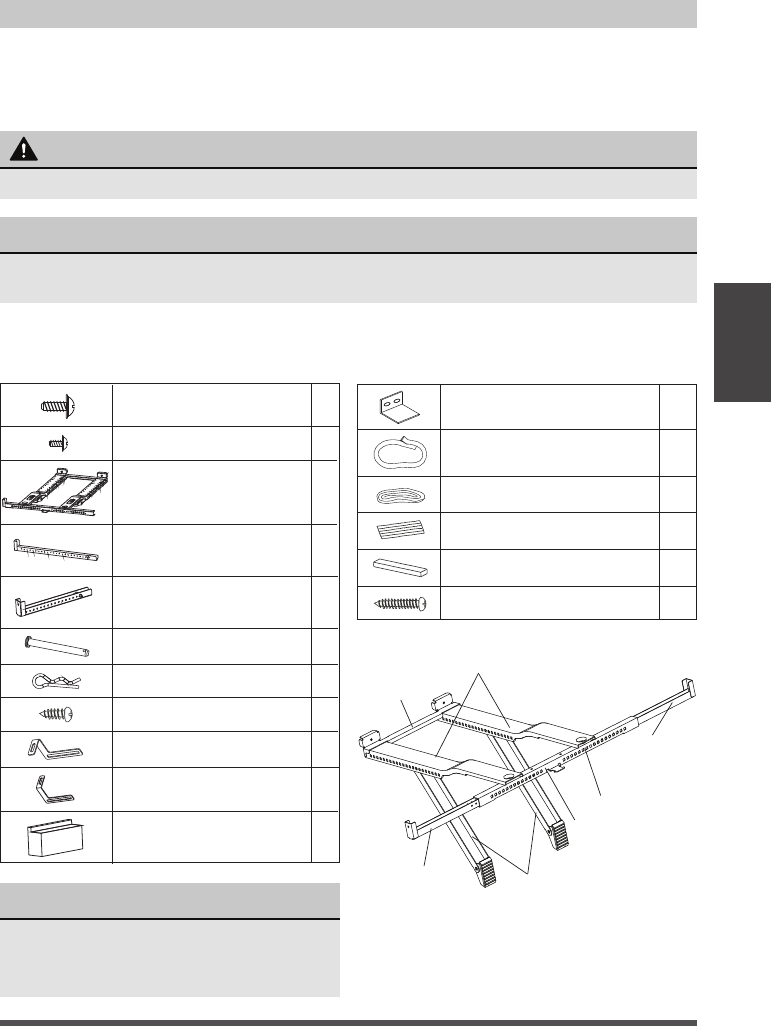
Angled Support
Arms
Right
Extension
Arm
Left Extension
Arm
Spring Push Pin
Main Support
Rear Cross
Brace
Horizontal Bracket
Required Installation Hardware Optional Installation Hardware
Side Arm Foam 2
Right Extension Arm – Short
(For 22”-26” windows)
1
Cotter Pin
2
Open Window Bracket – LH 1
Open Window Bracket – RH
1
Main Support Pin
2
Right Extension Arm
(For 26”-36” windows)
1
1Main Bracket
1/2” Type B Screw 2
1/4” Type B Screw 2
1/2” Type A Screw 3
Window Sash Lock
Thick Window Sash Seal Foam
Thin Window Sash Seal Foam
Miscellaneous Sealing Foam
Additional Side Arm Foam
1” Type A Screw 2
2
1
1
1
1
WARNING
Bracket should only be used for its intended purpose. If not, the warranty will be voided.
Page 16
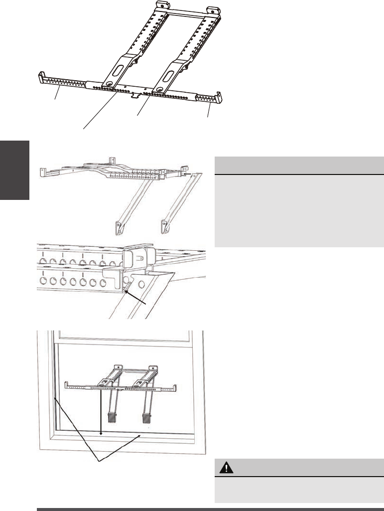
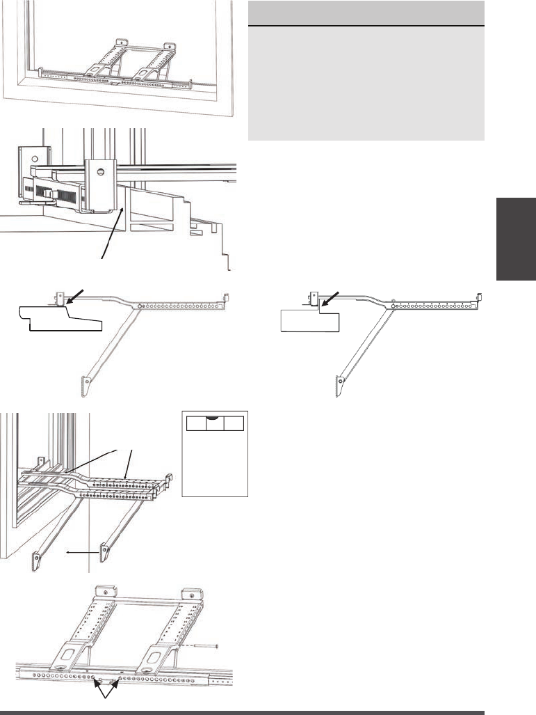
NOTICE
The Angled Support Arms should
come installed into the Main Supports
from the factory.
The small tabs on the sides of the
Angle Support Arms must sit on the
inside bottom of the Main Support.
On a flat surface such as a table,
press the spring push pin and adjust
the Left Extension Arm to the Left
side of the Horizontal Bracket.
Then install the Right Extension Arm
into the Right side of the Horizontal
Bracket. These will be adjusted in a
later step.
For windows where the front of the
bracket to sit on the window sill,
adjust the extension arms to your
window sill width. For windows
where the front of the bracket will
rest against the vinyl lip, these arms
will be adjusted in a later step.
A. Before placing the bracket in the
window, allow the Angled Support Arms
to rotate down and make sure they
don’t fall out of the Main support arms.
Place the support bracket assembly in
your window opening on the bottom
windowsill. The Horizontal Bracket and
Extension Arms must be located on the
indoor side of your window frame.
For installations where the bracket sits
on the window sill, secure the bracket
to the window (reference Step E).
Spring Push Pin
Horizontal Bracket
Right
Extension
Arm
Left
Extension
Arm
WARNING
Maintain control of the bracket until
installation is complete.
Window Frame
Installation
Instructions
Page 17
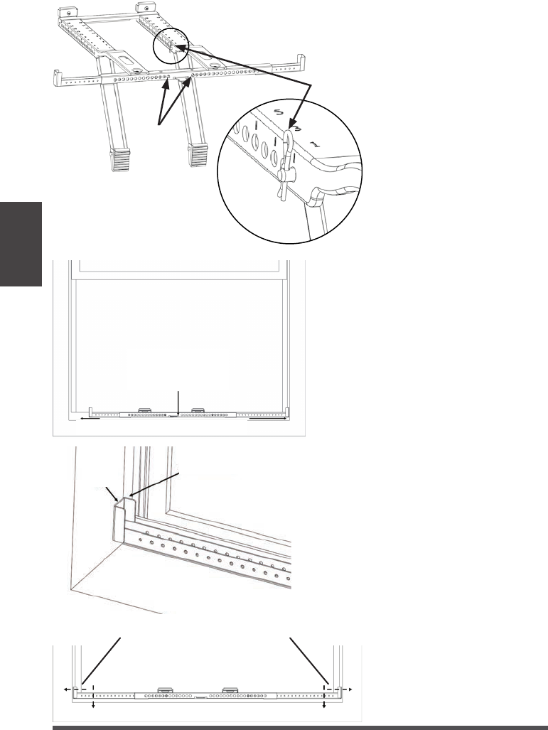
NOTICE
The front of the Support Bracket
should be located on the indoor side
of the window frame (refer to image
on the left).
Do not place the Horizontal Bracket
and Extension Arms inside the Window
Track where the window sash sits.
B. Move the Angled Support Arms
toward the exterior wall until the
Angled Support Feet touch the
wall. Place a level on a flat area of
the bracket and adjust the Angled
Support Arms so the bracket is
tilted downwards toward the
outdoors to allow condensate to
drain out. The proper angle is
when the level reads 1/4 bubble
(reference image for 1/4 bubble).
Indoor Side Window Frame
C. Insert the Main Support Pin through
the Main Support holes and Angled
Support Arm holes to secure the
Angled Support Arm. Repeat for the
other Angled Support Arm using
the numbers stamped on the Main
Support to help place both Angled
Support Arms in equal locations.
Here is what
1/4 bubble on
the level
should look
like.
Depending on the
level used, place at
either location below
to check level.
Wooden Windows
INSIDE
OUTSIDE
INSIDE
OUTSIDE
Vinyl-Clad Windows
Vinyl Lip
Installation
Instructions
Spring Pin Locks
Page 18
D. After securing both
Angled Support Arms,
check the level and ensure
the bracket feels secure.
Minor adjustments may be
needed.
Once secured, insert the
Cotter Pins into the Main
Support Pins.
E. Center the Support Bracket with the
center of the window. Note, due to
the design of the Air Conditioner, the
Support Bracket is biased to the left.
Once centered, extend the Left and
Right Extension Arms until they touch
the side of the windowsill and are in
front of the side window frame.
Secure the bracket to the window
with a screw at the end of each
extension arm as shown. Holes at the
end or bottom of the Extension Arms
can be used to secure the Support
Bracket to the window.
Window Frame Side
Window
Side
Center this part of the
bracket with the center
of the windows.
Extend the Extension Arms until they touch the
Windowsill and the Spring Pin locks in place.
Use the provided 1/2” Type A screws.
NOTE: Drill 1/8” pilot holes before
screwing into the window sill.
Installation
Instructions
Cotter Pin
Spring Pin
Locks
Page 19
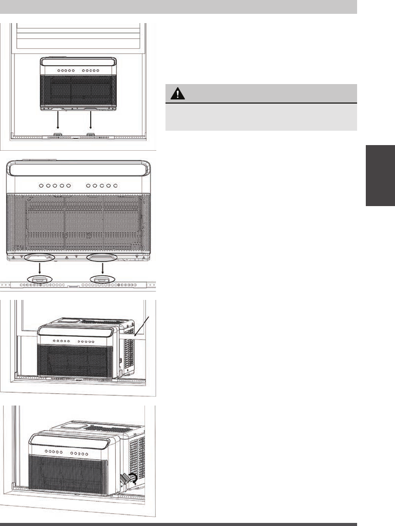
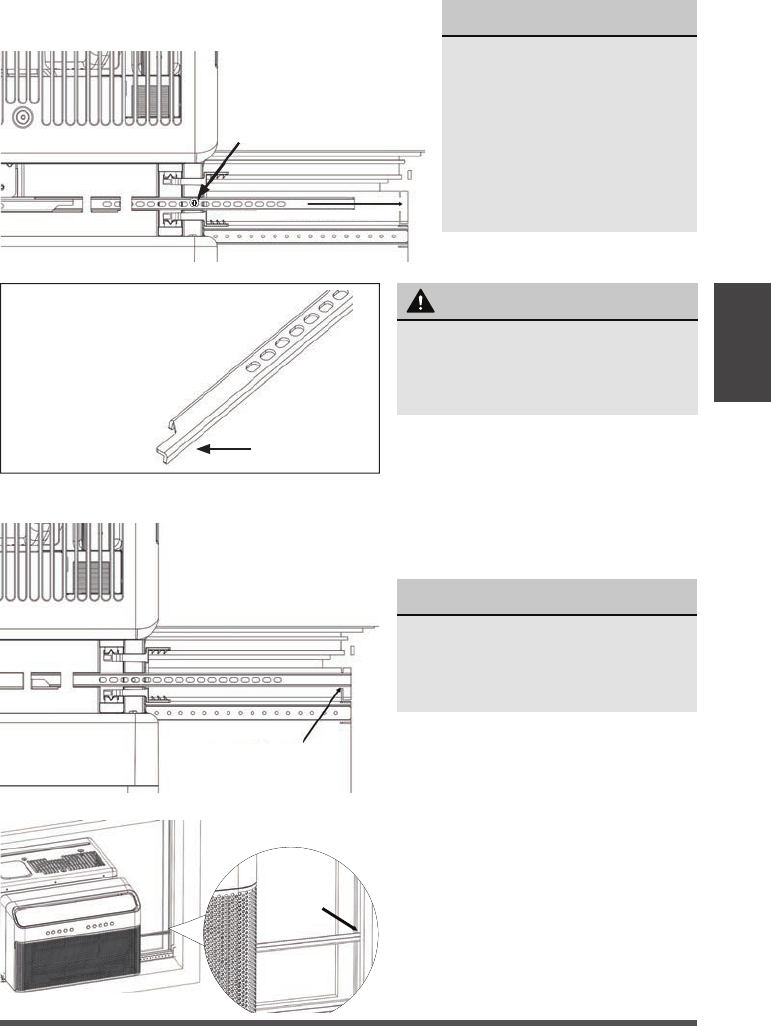
2. SECURE THE UNIT ON THE BRACKET
A. Set the air conditioner on top of the
support bracket. Ensure the grooves on
the bottom of the air conditioner align with
the Main Supports. Using a level, check for
proper tilt towards the outside.
B. Fold both Side Arm Hinges down and
measure the distance between the Side
Arm Hinge and the Window Frame.
WARNING
Do not leave the unit unattended during
installation.
Installation
Instructions
Pull the window down into the slot to
help align the unit in the correct location.
Keep the window partially inserted into
the window slot to help support the air
conditioner during installation.
Page 20
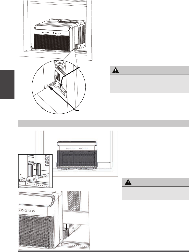
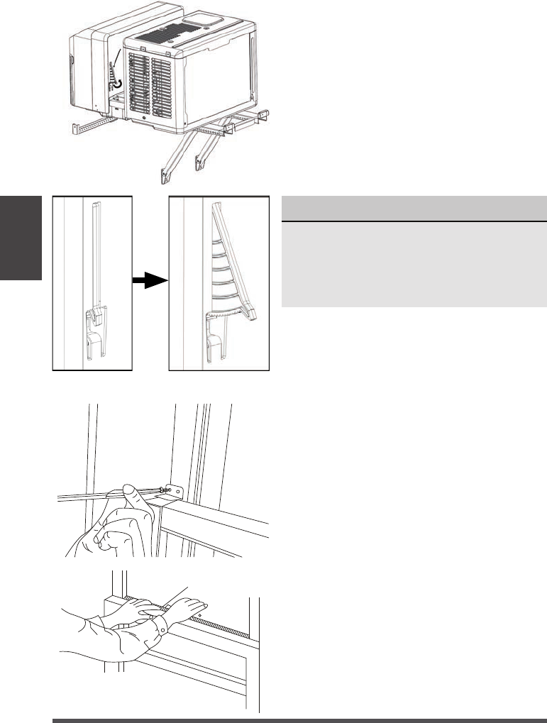
D. Measure the distance between
the Side Arm Hinge and the
closest part of the window
frame in line with the Side Arm.
Add 1/4” to this distance and cut
the Side Arm Foam to length.
Insert the Side Arm Foam
into the Side Arm Hinge and
repeat for the other side.
WARNING
Failing to install the Open Window
Brackets could cause injury or
property damage.
E. You must extend the Anti-Tip Brackets into
the Window Track Opening (the vertical track
that your window slides up and down in) until
they touch the window frame.
Secure the Anti-Tip Bracket in place with the
provided phillips screw. The air conditioner
may need to be adjusted front to back so
the Anti-Tip Brackets align with the Window
Track Opening.
C. You must install the Open Window
Brackets using the provided screws
shown here.
-or-
For installations where the bracket
sits on the window sill or a storm
window spacer – Use the provided 1”
Type A screw to secure the bracket
to the window sill.
NOTE: Drill 1/8” pilot holes before
screwing into the window sill.
WARNING
Do not leave the unit
unattended during installation.
Installation
Instructions
Use the 1/2”
Type B screw.
Use the 1/4”
Type B screw.
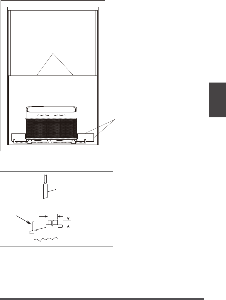
3. SEAL AND CLOSE THE WINDOW
Page 21
NOTICE
For Window Track Openings
1/2” or less, remove the
Anti-Tip Brackets and rotate
them so the smaller end of
the bracket can be inserted
into the Window Track
Opening. THEY MUST STILL
BE INSTALLED, so keep
both Anti-Tip Brackets.
NOTICE
Side Arm Foam removed from
image for illustrative purposes.
Keep foam in place during Anti-
Tip Bracket installation.
WARNING
You must extend the Anti-Tip
Brackets into the Window Track
Opening. Failure to follow this
warning may cause serious injury.
Top view
Anti-Tip Bracket
Installed in Window
Track Opening
The images to the left show what a
properly installed Anti-Tip Bracket into
the window track should look like.
The images to the left show what a
properly installed Anti-Tip Bracket into
the window track should look like.
This side
faces indoors
If the Anti-Tip Brackets
need to be rotated, this is
the correct orientation
Installation
Instructions
Top view
Extend into Window Track
Remove the factory installed 1/2”
screw and extend the Anti-Tip
Brackets into the window track.
Secure the Anti-Tip Brackets by
re-using the factory installed 1/2”
screw. Failing to use this screw
could damage the air conditioner.
Top of Unit
Page 22
To secure lower sash in place, attach right
angle sash lock with 1/2” Type A Screws as
shown.
F. Close the window and extend both
window locks located in the window slot
to prevent the window from opening. Be
sure to fully extend the locks so that they
come in direct contact with the window.
NOTICE
For additional security, you may use the
provided window locking hardware and lock
the window in place using the sash lock.
Also note that if you want to raise your
window, this lock will need to be removed.
FOAM SEAL
Cut window sash seal foam and insert it in the
space between the upper and lower sashes.
Installation
Instructions
Page 23
Review the installation and check for
any gaps or openings to the outdoor
air. Cover these gaps with the provided
foam ensuring no outdoor air leaks
inside. See image for areas to check
for gaps.
Use the window sash seal foam to
seal between the windows
Check for
Check
for Gaps
Use the thick window sash seal
foam to seal between the windows
Installation
Instructions
IF AC IS BLOCKED BY STORM WINDOW
SASH
OUTSIDE INSIDE
1-1/2" min
(38 mm)
Board thickness as
required, for proper
pitch to rear, along
entire sill. Fasten
with nails or screws.
Storm window
frame or other
obstruction.
Add wood as shown, or remove
storm window before air conditioner
is installed.
If storm window frame must
remain, be sure the drain holes or
slots are not caulked or painted
shut. Accumulated rain water or
condensation must be allowed to
drain out.
You must secure the support
bracket to the added wood piece
using the provided 1” Type A
Screws. Refer to the Open Window
Bracket installation step.
Page 24
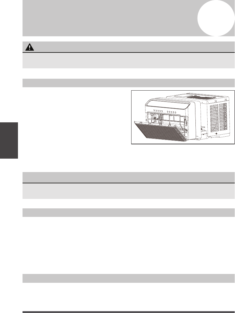
Air Filter Cleaning
Cabinet Cleaning
Winter Storage
The air filter should be checked at least
once every two weeks to see if cleaning
is necessary. Trapped particles in the filter
can build up and cause an accumulation
of frost on the cooling coils and reduce
performance.
• Grasp the filter by the center and pull
up and out.
• Wash the filter using warm water. Rinse
filter thoroughly.
• Be sure to unplug the air conditioner to prevent shock or fire hazard. The cabinet and
front may be dusted with an oil-free cloth or washed with a cloth dampened in a solution
of warm water and mild liquid dishwashing detergent. Rinse thoroughly and wipe dry.
• Never use harsh cleansers, wax, or polish on the air conditioner.
• Be sure to wring excess water from the cloth before wiping around the controls.
Excess water in or around the controls will cause damage to the air conditioner.
• Plug in air conditioner.
Care and
Cleaning
3
Care and Cleaning
CAUTION
Clean your air conditioner occasionally to keep it looking new. Be sure to unplug the
unit before cleaning to prevent shock or fire hazards.
NOTICE
Never use hot water over 104°F (40°C) to clean the air filter. Never attempt to
operate the unit without the air filter.
If you plan to store the air conditioner during the winter, remove it carefully from the
window according to the installation instructions. Be careful not to spill any potentially
standing water from the unit’s base pan. If water is present, carefully drain it. Cover the
unit with plastic or return it to the original carton.
• Gently shake excess water from the filter. Be sure the filter is thoroughly dry before replacing.
• Instead of washing, you may also vacuum the filter clean rather than washing.
Page 25
Troubleshooting
Tips
4
Troubleshooting Tips
Before calling for service, review this list. It may save you time and expense. This list
includes common occurrences that are not the result of defective workmanship or
materials in this appliance.
Problem Solution
Air conditioner
does not s
tart.
Wall plug disconnected. Push plug firmly into wall outlet.
Circuit breaker tripped. Reset circuit breaker.
Check if the light on the plug is on. If it is off, press the RESET
button.
Power is OFF. Turn power ON.
Unit turned off and then on quickly. Turn unit off and wait 3 minutes
before restarting.
Air from unit
does not feel
cold enough.
Room temperature below 62°F (17°C). Cooling may not occur until
room temperature rises above 62°F (17°C).
Temperature sensor behind the air filter is touching the cold coil.
Try to move it so it does not contact the cold coil.
Reset to a lower temperature.
Compressor shut-off by changing modes. Wait approximately
3 minutes and listen for compressor to restart when set in the
COOL mode.
Check for potential obstructions blocking the outdoor intake/
exhaust. Clear any obstructions.
Air conditioner
cooling, but
room is too
warm- ice
forming on
cooling coil
behind air filter.
Outdoor temperature below 64°F (18°C). To defrost the coil, set to
FAN ONLY mode.
Air filter may be dirty. Clean filter. Refer to Care and Cleaning
section. To defrost, set to FAN ONLY mode.
Thermostat set too cold for night-time cooling. To defrost the coil,
set to FAN ONLY mode. Then, set temperature to a higher setting.
Air conditioner
cooling, but
room is too
warm- NO ice
forming on
cooling coil
behind air filter.
Dirty or restricted air filter. Clean filter. Refer to Care and Cleaning
section. To defrost, set to FAN ONLY mode.
Temperature is set too high, set temperature to a lower setting.
Air directional louvers positioned improperly. Position louvers for
better air distribution.
Front of unit is blocked by drapes, blinds, furniture, etc. - restricts
air distribution. Clear obstruction in front of unit.
Any open doors, windows, or registers may allow cold air to escape.
Close any doors, windows, or registers.
The room may be too warm. Allow additional time to remove
“stored heat” from walls, ceiling, floor and furniture.
Page 26
Troubleshooting
Tips
Problem Solution
Air conditioner
turns on and off
rapidly.
Dirty air filter- air restricted. Clean air filter.
Outside temperature extremely hot. Set FAN speed to a higher
setting to bring air past cooling coils more frequently.
Check for potential obstructions blocking the outdoor intake/
exhaust. Clear any obstructions.
Noise when unit
is cooling.
Air movement sound. This is normal. If too loud, set to a slower FAN setting.
Window vibration - poor installation. Refer to installation
instructions or check with installer.
Water dripping
INSIDE when
unit is cooling.
Improper installation. Tilt air conditioner slightly to the outside to
allow water drainage.
Refer to installation instructions - check with installer.
Water dripping
OUTSIDE when
unit is cooling.
Unit removing large quantity of moisture from humid room. This is
normal during excessively humid days.
Remote sensing
deactivating
prematurely
(some models).
Remote control not located within range. Place remote control
within 20 feet & 180°, radius of the front of the unit, and pointed
in the general direction of the air conditioner unit.
Remote control signal obstructed. Remove obstruction.
Room too cold. Temperature setting too low. Increase temperature setting.
Noise when unit
starts.
A “da-da” sound may occur for thirty seconds when the unit is
turned on due to the compressor starting. It is normal.
Unit will not
connect to WiFi
or App does not
work.
For additional support and troubleshooting tips, follow the link in
this QR code:
Window does
not insert into
the U-shaped
slot.
Ensure that the “U-shaped” slot is in line with the window, if not,
align the slot with the window.
Ensure that the unit is not slanted too much to cause interference with the
top of the unit. Reference steps on pages 15-23 for those instructions.

Page 27
5
Warranty
Warranty
Air Conditioner Limited Warranty
Your product is protected by this Limited Warranty:
Warranty service must be obtained from Midea Consumer Services or an authorized Midea servicer.
Warranty
• One Year Limited Warranty from original purchase date. Five Year Limited Sealed System Warranty (includes
components containing refrigerant) from original purchase date. Three Year Limited Compressor Warranty
from original purchase date.
Midea, through its authorized servicers will:
• Pay all costs for reparing or replacing parts of this appliance which prove to be defective in materials or
workmanship.
Consumer will be responsible for:
• Diagnostics, removal, transportation and reinstallation cost required because of service.
• Costs of service calls that are a result of items listed under NORMAL RESPONSABILITIES OF THE CONSUMER**
Midea replacement parts shall be used and will be warranted only for the original warranty.
NORMAL RESPONSABILITIES OF THE CONSUMER**
This warranty applies only to products in ordinary household use, and the consumer is responsible for the items
listed below:
1. Proper use of the appliance in acordance with instructions provided with the product.
2. Routine maintenance and cleaning necessary to keep the good working condition.
3. Proper installation by an authorized service professional in accordance with instructions provided with the
appliance and in accordance with all local plumbing, electrical and/or gas codes.
4. Proper connection to a grouded power supply of sufficient voltage, replacement of blown fuses, repair of loosen
connections or defects in house wiring.
5. Expenses for making the appliance accessible for servicing.
6. Damages to finish after intallation.
EXCLUSIONS
This warranty does not cover the following:
1) Failure caused by damage to the unit while in your possesion (other than damage caused by defect or
malfunction), by its improper installation, or by unreasonable use of the unit, including without limitation, failure to
provide reasonable and necessary maintenance or to follow the written installation and Operating Instructions.
2) Damages caused by serviced performed by persons other than those authorized by Midea customer service; or
external causes such as abuse, misuse, inadequate power supply or acts of God.
3) If the unit is put to commercial, business, rental, or other use or application other than for consumer use, we make
no warranties, express or implied, including but not limited to, any implied warranty of merchantability or fitness
for use or purpose.
4) Products without original serial numbers or products that have serial numbers which have been altered or cannot
be readily determined.
NOTICE: Some states do not allow the exclusions or limitation of incidental or consequential damages. So this
limitation or exclusion may not apply to you.
IF YOU NEED SERVICE
Keep your bill of sale, delivery slip, or some other appropriate payment Record.
The date on the bill establishes the warranty period, should service be required.
If service is performed, its your best interest to obtain and keep all receipts.
This written warranty gives you specific legal rights. You may also have other rights that vary from state to state.
Service under this warranty must be obtained by following these steps, in order:
1) Contact Midea Consumer Services or an authorized Midea services at 1 866 646 4332.
2) If there is a question as to where to obtain service, contact our consumer relations Departament.

Free 3 months
extension* of the
original limited warranty
period! Simply text a
picture of your proof of
purchase to:
1-844-224-1614
*The warranty extension is for the
three months immediately following
the completion of the product’s
original warranty period.
